How To's
The Lab does have a Git Hub page- https://github.com/margoliashlab
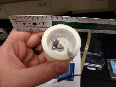
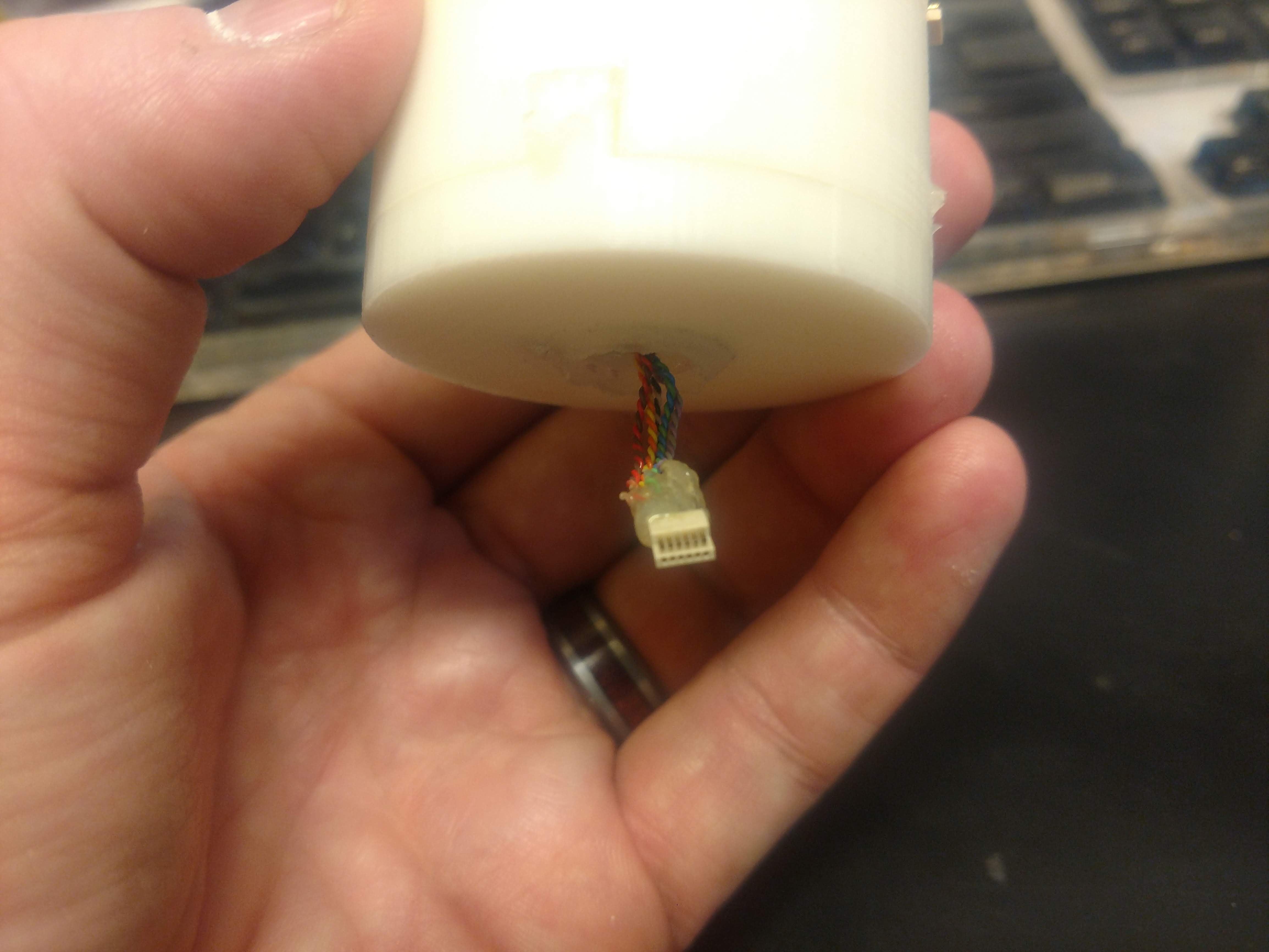
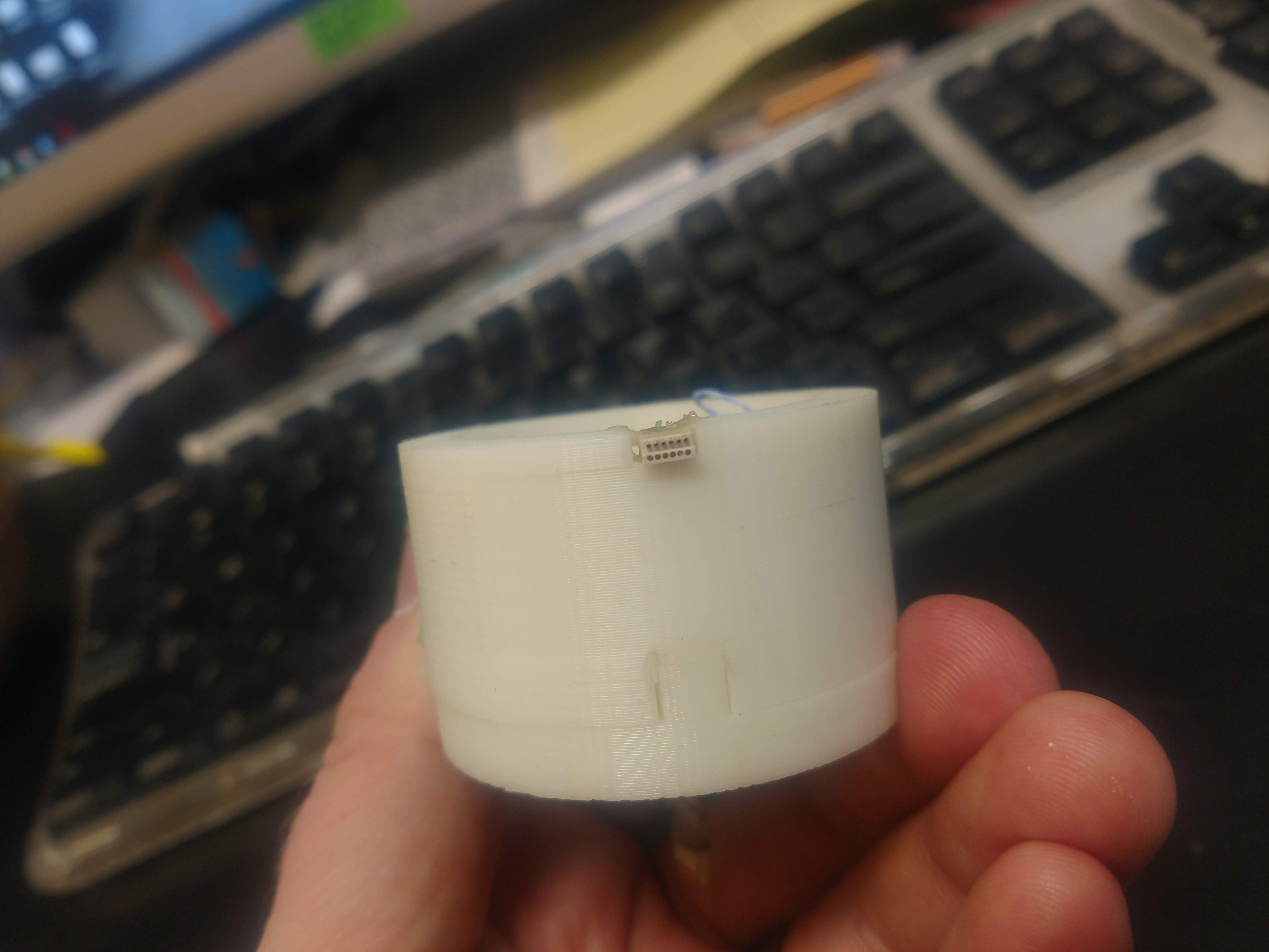
Lab- built 10 channel Commutators
Vendor Part Number Description Quantity
_________________________________________________________________________________________________________________________
McMaster-Carr    4262T9 Premium Flanged Bearing, Flanged Double Shielded for
                        1/8in  Shafted Diameter, 3/8in OD                              1
McMaster-Carr  92470A056 Pan Head Phillips Screw for Sheet Metal, 18-8 Stainless
                        Steel, Number 1 Size, 7/16in Length                            2
Omnetics Connector Corporation PZN-12-DD Polarized Nano Connector, 12 Contacts,
                        Straight Tail                                                  2
Moog, Inc           AC259-10S   Brush Block Assembly                                   1                                                               1
Moog, Inc           AC2690-10S  Slip Ring Assembly                                     1                                                              1
_____________________________________________________________________________________________________
Steps-
- Order the parts from Moog, Inc and Omnetics (it will take weeks for them to arrive)
- Print the model
- be very aware that the 3D print will have 2 pieces
- The model will not have a top
- The center hole will have a small recessed area to accept the flanged bearing
- All tolerances are tight between the model, bearing and slip ring assembly
- be very aware that the 3D print will have 2 pieces
- Push flanged bearing into center hole, make sure the flange is flush at the top.
- A drop of superglue can be used to help secure the bearing but as mentioned, it is tight.
- Pull the wires of the slip ring assembly through the bearing and make sure the slip ring is fully seated in the bearing, again- remember this will be tight (add a tiny drop of super glue between the bearing and slip ring.
- Place the brush block over the slip ring without the still wires touching the slip ring.
- Slowly pull the brush block away from the slip ring, about as far as the inside of the brush block just NOT covering the flanged bearing.
- Mark the screw holes and or add a small drop of super glue
- Remove the brush block and predrill your holes
- Replace the brush block and and screw in place
- Solder your wires to the brush block according the the wiring diagram for the nano connector
- You can try doing twisted pairs but found that not to be necessary
- Slide a spring wire over the wires exiting below the commutator and cut the spring slightly shorter than the wires.
- Strip the wires, I found heat works well- even a soldering iron can do that.
- Solder nano connector, in the opposite way as the top wires
- Sadly, twisted pairs helps give some rigidity to the bundle of wires
- Test that all connections work correctly
- Add some epoxy to protect the soldered parts of the connectors and glue the top connector in the groove on the top of the commutator!
- Done- with some practice this can be done in about 2 hours

IMG_20180815_132144919-2gdtax7

IMG_20180815_132136212-22cspxa
IMG_20180815_132127338-29ion3q
IMG_20180815_132105745-248n1hu

IMG_20180815_132055578-2n6w8sy
************************************************************************************************************************
How to- Build a manual Microdrive

- Parts needed:McMaster Carr:
Brass Round Head Slotted Machine Screw, 00-90 Thread, 1/2″ Length, packs of 10
$7.12 pack
Easy-to-Form 260 Brass, Strip, 0.016″ Thick, 1/4″ x 12″
$1.06 each
Brass Hex Nut, 00-90 Thread Size, 5/64″ Wide, 3/64″ High, packs of 25
$9.20 pack
Digikey
3 pin. Connector Header: 2163S-03-ND
How to build:
All drives are made from the same basic elements: a moving part, which carries the electrode and a fixed part, which is anchored to the skull. An ideal microdrive allows smooth but long enough travel of the electrode in multiple small steps, is sturdy enough to prevent accidental movement of the electrode, easy to manipulate by the experimenter without interfering with the animal’s behavior, small in size and light in weight. As a result of these competing requirements, different drives suite different applications.
Only 4 parts are needed to build our basic drive: a brass flat head screw, a matching nut, a plastic bridge prepared from a single row pin header and two custom-cut brass plates.
- Break a 3-pin piece from the header
- Gently pull out the middle pin.
- Enlarge the hole by drilling through it with a drill bit size #55.
- Cut a thread using the 00-90 tap.
- Cut two pieces out of the brass plate.
- File the edges of the plates with a Dremel.
- Drill a hole in the middle of both pieces using a drill bit size #65.
- Assemble the drive pieces so that the brass plates are touching the pins. To accomplish this, insert the brass screw through, successively, the brass plate, the threaded pin header hole, the second brass plate, and the nut. Tighten the screw gently so that the assembly becomes stable.
- Solder the pin ends to the brass plates.
- File the protruding end of the screw.
- Solder the nut to the screw. Be careful not to solder the nut to the brass plate.
- Test the movement of the drive: turn the screw clockwise to elevate the plastic bridge.
Affixing the probe to the microdrive
- Using a razor blade, cut multiple grooves into the bridge to create a rugged surface.
- Appose the probe to the bridge of the drive. This procedure is best done under an operating microscope, by holding the drive with a clamp and adjusting the probe by a micromanipulator so that the shanks are perfectly parallel with the drive screw. This ensures that during advancement, the probe shanks move into brain tissue without ‘cutting’ through it. The exact depth of the probe tips relative to the base of the drive should be determined at this stage, taking into consideration the depth of the target structure from the surface of the skull.
- The probe is then fixed to the bridge with grip cement.
- Optional: for visualizing the probe track in the brain, DiI solution (1-2% diluted in ethanol) can be applied to the back of the probe at this stage.
Imput from Derek Zaraza:
Attach hypodermic needles to the shuttle with electrode(s) and only the electrodes go into the brain. you should make sure that the electrodes stick out of the hypodermic tube enough to reach the desired target before the tubing hits the skull or brain. if you are using the traditional glass coated electrodes from the lab you may need to use individual hypodermic tubes for each electrode as the glass can easily crack if the electrodes rub together. Derek does not put any wax above the surface of the brain just a bit of silicon gel for sharp electrodes. when he implants it, place them just above the target area to minimize that amount of throw necessary on the drive. for using neuronexus probes i followed hamish’s procedure of pouring a mixture of bone wax and silicon gel over the brain after implanting the array above the target area.
Derek attaches the connector to the skull separately from the drive wherever there is room and where the tether won’t pull the head to the side. the tether is recoverable after using forceps and the swedish cutting tools to get most of the stuff off then a quick soak in acetone. in order to prevent the leads from the electrodes from undergoing too much pressure during implantation and use i extend the electrodes to their maximum depth and then epoxy them to the top of the drive
(away from the screw). The connector can just dangle from that point during microdrive implantation and once the microdrive is secure you can place the grounding wire and connector. i’ve found that putting the grounding wire all the way in the brain seems to produce a better signal. it’s also helpful to make sure the lead from the grounding wire is fully encased in acrylic by the end of implantation to prevent wiggling.
as far as protecting the drive and the electrodes from bird feet and the rest of the environment i really like the results from making a sleeve of transparency paper held together with absorbent bandage tape. it can be strengthened with a layer of acrylic over the exterior tape. i’m attaching a few images of the implantation process showing an oversized stand of bone wax under the drive (i was overcautious and made the electrodes too long on that drive) as well as the protective shield.
DIY Bone Wax- Bone wax is a mixture of beeswax and paraffin. With a little heat mix up 1 small sheet of beeswax with almost half the amount of paraffin wax, add to this about 3-4 ml of paraffin oil and mix. Should be a paste consistency.