1. Panels that lack a viability dye.

2. Panels that don’t have fluorophores spread across the lasers.

If one fluorophore spills into a detector assigned to a second fluorophore, then compensation must be used to address the spillover. The image above shows two compensation matrixes for two small panels. When three fluorophores on the same laser are used together (top panel), a lot of compensation must be applied to deal with the spillover between these fluorophores. In contrast, a four color panel with one color per laser requires almost no compensation (bottom panel). Will the three color panel produce totally unusable data? No, it’s possible to get useable data – assuming the compensation is correct. However, by putting all of the markers on the same laser the experiment is much more difficult than it needs to be. In order to calculate compensation, you must bring good quality compensation controls that follow all of the rules, calculate the compensation, and check the compensation to confirm it is correct. For new flow cytometrists (or even experienced ones), this just means more steps, more time, and more opportunities to make mistakes. Since new flow cytometrists are already pretty overwhelmed with things to think about in a flow cytometry experiment, I recommend avoiding compensation or using as little as possible in order to make things as simple as possible.
It’s always best to choose fluorophores that have minimal or no spillover – and in the best case scenario compensation can be avoided altogether. To follow panel design theory and create the easiest panel, my simplest recommendation is to spread out the fluorophores across the detectors – usually starting by using the first detector of each laser. For a 4-laser cytometer, that typically means BV421, FITC, PE, and APC are used in a 4-marker panel. To expand the panel beyond 4 markers, you can choose 2 markers per laser, then keep adding fluorophores keeping them spread across the lasers. With panels larger than 8-10 markers, it’s still a good idea to try to minimize spillover between fluorophores, but for a different reason which I will explain in my next point.
3. Panels smaller than 10 markers that contain PE-Cy5, PE-Cy5.5, both PerCP-Cy5.5 and PE-Dazzle 594, or both BV605 and BV650.

In the above image I’ve calculated the spillover-spreading matrix (SSM) using single stained compensation beads for two similar panels – the goal is to choose fluorophores that result in lower values in the SSM. If we add up all the values in the SSM, you can see that a panel with BV605, BV650, PerCP-Cy5.5 and PE-Dazzle594 has an overall value of 45.33, whereas switching out BV650 and PE-Dazzle594 reduces the overall value to 25.52. Again, I’m not saying that these fluorophores can never be used together, it’s just more challenging. I always recommend taking the easiest route possible!
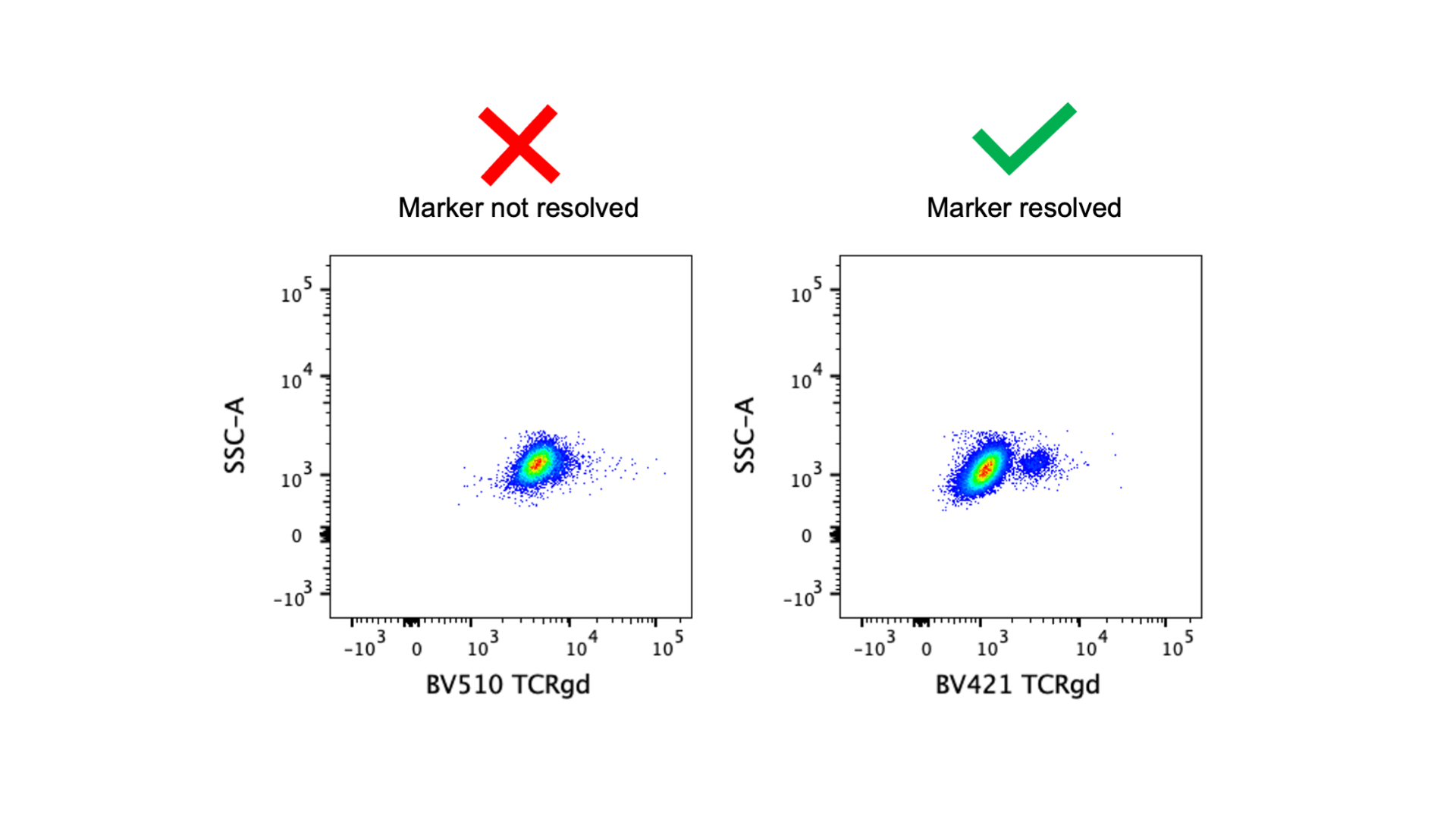
4. Low expressed markers paired with dim fluorophores.

For the best resolution of markers, low expressed markers should always be paired with bright fluorophores. The image above demonstrates that if the anti-TCRγδ antibody is tagged with a dim fluorophore (BV510) the positive population cannot be resolved, but moving it to a much brighter fluorophore (BV421) fixes the problem. In the basic 4-color panel (BV421, FITC, PE, APC), all fluorophores are pretty bright, so you don’t need to worry too much about matching marker expression level and fluorophore brightness. Note: FITC is the dimmest of those four fluorophores, and Pacific Blue and eFluor450 can be alternatives to BV421 but they are dimmer fluorophores. Fluorophore brightness is also dependent on cytometer configuration, so make sure you are familiar with your cytometer! You can find brightness indexes for our fortessas here. With larger panels, it’s more important to take panel design theory into consideration and save the brightest fluorophores for the low expressed markers.
Summary
These are my four “red flags” for identifying panels that may be sup-optimal. Again, I want to stress that panels with these issues don’t necessarily produce bad results, they are just more likely to have issues with marker resolution or false positives. Alternatively, these problematic panels introduce unnecessary challenges and for new flow cytometrists this provides opportunities to make mistakes. For a more in-depth discussion of panel design, check out my Flow Basics 2.3 course (video and slides available). Stay tuned in two weeks for my post on red flags for experiment design!
Update: You can read part 3 here!

This blog is exactly what I needed to see. We have one large panel for our Symphony (20 colors) that follows the rules except for the high perpetrators of BV605 and BV650. Your writing is very concise and easy to understand! You had mentioned you are available as a consultant–how do we go about setting up a meeting with you?
Please email me at LJohnston@bsd.uchicago.edu with a brief description of what you’d like me to help you with and we can set up a meeting!
Your blog is extremely great!